
JA-82M
Service instructions for JA-82M
1 Installation
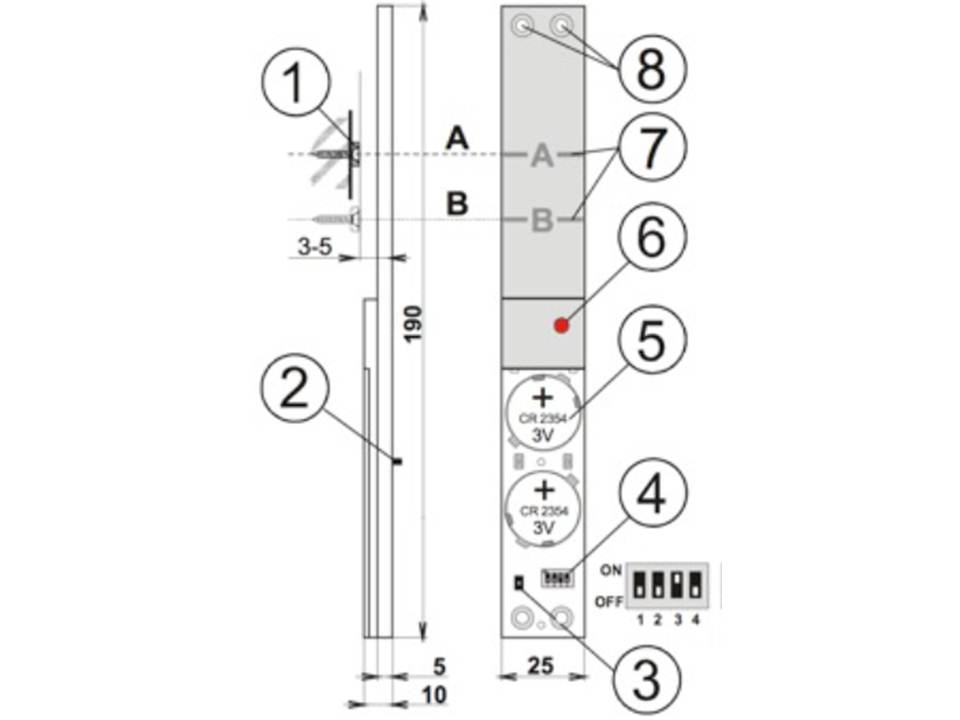
1. magnet, 2. rear tamper sensors, 3. tamper sensor valve, 4. DIP switches, 5. battery, 6. LED indicator, 7. pass strips, 8. screw holes.
LED Indicator - 15 minutes after closing the battery cover, the LED
indicates detector triggering (a flashing light indicates window opening, a long light indicates both tamper sensors are triggered).
1. Find a suitable location for the detector so that the magnet faces the A (or B)
when the window or door is closed.
2. Avoid placing the detector directly on a metal surface because metal can affect the
operation of the magnetic sensor and radio communication. This
can usually be achieved by placing the detector on the hanging side of the window or door
. Further, avoid installing the detector at the bottom of the frame
of the window or door because of possible condensation water
3. Screw the magnet onto the moving part of the window according to the following drawing.
Use a non-metallic mounting plate if the space in the frame is too large.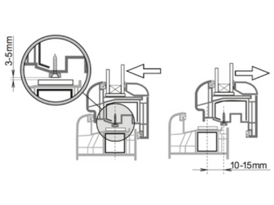
4. Unscrew the battery cover and screw the detector so that the magnet falls across the A (or B) line against
when the window or door is closed. See drawing. Be
careful and do not use too much force when tightening the detector or the
plastic housing may be damaged.
5. You can use the supplied long plastic strips to ensure that the
place where the detector is to be secured is sufficiently flat. After the detector
is installed, at least one tamper detector on the back should be permanently
closed (pressed).
6. Carefully try that the detector (magnet) does not form an obstacle when closing the
window or door.
7. If everything is OK, the functionality of the detector can be configured (See
DIP switches below).
8. Go into login mode on the central unit (or on a receiver). Then insert the
button cell batteries into the detector and screw on the cover (2 screws). After
connecting the battery, the detector will automatically send a login signal. Up to
10 seconds delay should be expected regarding the response of the
detector to removing the magnet, closing or pressing and releasing the
tamper sensors.
9. After the detector is registered, you can check its operation. On the Jablotron OASiS
central unit, you should also check the signal strength.
switches
| Number | Off | On |
| 1 | Sabotage sensors rear off | Sabotage sensors rear on* |
| 2 | Permanent status display window/door | Display window/door open only** |
| 3*** | System provides entry and exit delay | System responds with instantaneous alarm |
| 4 | No function | No function |
The default settings are in bold
*To detect intrusion, it must be set to ON.
** Switching ON is suitable for bedrooms, where windows and doors are left open for ventilation at the time that the central unit is on.
*** This setting is applicable if the detector is used with an OASiS central unit
with a pre-programmed natural response for the address of the detector.
2 Testing the detector
Up to 15 minutes after closing the cover of the detector, the LED indicates the triggering of the detector as follows:
Short flash
air pressure change (deformation of glass)
Long flash
glass breakage detection (alarm)
Adjusting the sensor
- By using proper tools or by using a hand protected with a glove
knock one by one on all windows that are to be secured
by the detector. A visible deformation of the glass should occur without causing damage.
- The deformation of the glass causes a change of air pressure in the room that causes the detector's LED to flash briefly.
- The sensitivity to air pressure can be adjusted using the potentiometer on the
circuit board. Turning counterclockwise increases the sensitivity. Avoid selecting too high a sensitivity as this may cause short battery life.
- The complete operation of the detector can be tested with a GBT-212 glass breakage simulator. After tapping on the glass, the simulator will automatically make a characteristic sound of breaking to trigger the detector.
3 Battery replacement
The batteries of the detector are checked regularly. If the battery voltage becomes too low then the installer or user is informed. The detector will continue to function however battery replacement should not be delayed more than 2 weeks. Always replace both batteries. We recommend that you use batteries of a highly qualified with (e.g. Panasonic). After the batteries are replaced, the operation of the detector should be tested.
Old batteries should not be thrown in the garbage but disposed of according to local regulations in force.
4 Removal of the detector from the system
When a detector is removed, the central unit reports the removal. The detector should first be removed in the central controller if the intention is to physically remove it.
5 Technical parameters
| Voltage: | Lithium battery type CR2354-2 pieces (3.0V, 1 Ah) power supply type C |
| Estimated battery life: | Approximately 3 years (at 5 times daily activation) |
| Communication band: | 868 MHz, OASiS protocol |
| Communication range: | Approximately 200m (in open field) |
| Dimensions: | 192 x 25 x 9 mm |
| Temperature range: | -10to +40 °C |
| Classification grade 2 according to: | EN 50131-1, EN 50131-2-6, EN 50131-5-3 |
| Complies with: | ETSI EN 300220, EN50131-2-6, EN 60950 -1 |
| Can be operated in accordance with: | ERC REC 70-03 FCC ID VL6JA82M |
Scope of operation according to EN 50131-1 II. internal space